Hyundai Venue: Front Suspension System / Front Stabilizer Bar. Repair procedures
Hyundai Venue (QX) (2020-2025) Service Manual / Suspension System / Front Suspension System / Front Stabilizer Bar. Repair procedures
| Removal |
| 1. |
Loosen the wheel nuts slightly.
Raise the vehicle, and make sure it is securely supported.
|
| 2. |
Remove the front wheel and tire (A) from front hub.
|


| 3. |
Disconnect the stabilizer link with the front strut assembly after loosening
the nut (A).
|


| 4. |
Remove the tie rod end ball joint.
|


| 5. |
Loosen the lower arm nut (A) and then remove the lower arm ball joint
by using SST(09568-1S100).
|


| 6. |
Loosen the bolt (A) and then disconnect the universal joint assembly
from the pinion of the steering gear box.
|


| 7. |
Remove the engine room under cover (A).
(Refer to Engine Mechanical System - "Engine Room Under Cover")
|
| 8. |
Remove the heated protector (A).
|

| 9. |
Remove the muffler rubber hanger (A).
|

| 10. |
Remove the roll rod bracket (C) by loosening the bolt (A), (B).
|

| 11. |
Remove the subframe by loosening the mounting bolts and nuts.
|


| 12. |
Loosen the mounting bolts and then remove the stabilizer bar (A).
|

| 13. |
Remove the stabilizer link.
|

| 14. |
Remove the bushing.
|

| Inspection |
| 1. |
Check the bushing for wear and deterioration.
|
| 2. |
Check the front stabilizer bar for deformation.
|
| 3. |
Check the front stabilizer link ball joint for damage.
|
| Installation |
| 1. |
Install in the reverse order of removal.
|
| 2. |
Check the alignment.
(Refer to Suspension System - "Alignment")
|
 Front Lower Arm. Repair procedures
Removal
1.
Loosen the wheel nuts slightly.
Raise the vehicle, and make sure it is securely supported.
2...
 Sub Frame. Repair procedures
Removal
1.
Loosen the wheel nuts slightly.
Raise the vehicle, and make sure it is securely supported.
2...
Other information:
Hyundai Venue (QX) (2020-2025) Owners Manual: Normal Maintenance Schedule
I : Inspect and if necessary, adjust, correct, clean or replace. R : Replace or change. *1 : The drive belt should be replaced when cracks occur or tension is reduced excessively. *2 : If TOP TIER Detergent Gasoline is not available, one bottle of additive is recommended...
Hyundai Venue (QX) (2020-2025) Owners Manual: Luggage Net Holder
To keep items from shifting in the luggage compartment, you can use the 4 holders located in the luggage board to attach the luggage net. Make sure the luggage net is securely attached to the holders in the luggage board. WARNING Avoid eye injury...
Categories
- Manuals Home
- 1st Generation Venue Owners Manual
- 1st Generation Venue Service Manual
- Automatic Door Lock and Unlock Features
- Operating Door Locks from Outside the Vehicle
- Trip Computer
- New on site
- Most important about car
Fuel gauge
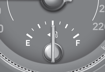
This gauge indicates the approximate amount of fuel remaining in the fuel tank.
Information
The fuel tank capacity is given in chapter 2. The fuel gauge is supplemented by a low fuel warning light, which will illuminate when the fuel tank is nearly empty. On inclines or curves, the fuel gauge pointer may fluctuate or the low fuel warning light may come on earlier than usual due to the movement of fuel in the tank.
Copyright © 2025 www.hvenueqx.com