Hyundai Venue: Motor Driven Power Steering / Steering Gear Box. Repair procedures
| 1. |
Loosen the wheel nuts slightly.
Raise the vehicle, and make sure it is securely supported.
|
| 2. |
Remove the front wheel and tire (A) from front hub.
|
Tightening torque :
107.9 - 127.5 N.m (11.0 - 13.0 kgf.m, 79.6 - 94.0 lb-ft)
|
| •
|
Be careful not to damage the hub bolts when removing
the front wheel and tire (A).
|
|

|
| 3. |
Disconnect the stabilizer link with the front strut assembly after loosening
the nut (A).
|
Tightening torque :
98.1 - 117.7 N.m (10.0 - 12.0 kgf.m, 72.3 - 86.8 lb-ft)
|
| •
|
When loosening the nut (A), fix the outer hexagon of
stabilizer bar link.
|
| •
|
Be careful not to damage the stabilizer link boots.
|
|

|
| 4. |
Remove the tie rod end ball joint.
| (1) |
Remove the split pin and nut (A).
|
| (2) |
Using SST(09568-1S100), separate the ball joint (B) from the
knuckle.
|
Tightening torque :
34.3 - 44.1 N.m (3.5 - 4.5 kgf.m, 25.3 - 32.5 lb-ft)
|


|
|
| 5. |
Loosen the lower arm nut (A) and then remove the lower arm ball joint
by using SST(09568-1S100).
|
Tightening torque :
68.6 - 80.4 N.m (7.0 - 8.2 kgf.m, 50.6 - 59.3 lb-ft)
|


|
| 6. |
Loosen the bolt (A) and then disconnect the universal joint assembly
from the pinion of the steering gear box.
|
Tightening torque :
M8 BOLT : 32.4 - 37.3 N.m (3.3 - 3.8 kgf.m, 23.9 - 27.5 lb-ft)
M10 BOLT : 49.0 - 58.8 N.m (5.0 - 6.0 kgf.m, 36.2 - 43.4 lb-ft)
|

| •
|
The clock springs inner cable may be damaged in case
the steering wheel moves. Make sure to put the steering
wheel in the center position.
|
| •
|
Lock the steering wheel in the straight ahead position
to prevent the damage of the clock spring inner cable.
|
| •
|
When assembling, insert the shark pin into the universal
joint york slot as the below illustration.

|
|
|
| 7. |
Remove the engine room under cover (A).
(Refer to Engine Mechanical System - "Engine Room Under Cover")
|
| 8. |
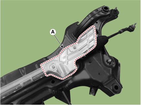
Remove the heated protector (A).

|
| 9. |
Remove the muffler rubber hanger (A).

|
| 10. |
Remove the roll rod bracket (C) by loosening the bolt (A), (B).
|
Tightening torque
(A) : 107.9 - 127.5 N.m (11.0 - 13.0 kgf.m, 79.6 - 94.0 lb-ft)
(B) : 49.0 - 63.7 N.m (5.0 - 6.5 kgf.m, 36.2 - 47.0 lb-ft)
|

|
| 11. |
Remove the subframe by loosening the mounting bolts and nuts.
| •
|
Set a transmission jack for safety.
|
|
|
Tightening torque :
176.5 - 196.1Nm (18.0 - 20.0 kgf.m, 130.2 - 144.7 lb-ft)
|

|
| 12. |
Loosen the mounting bolts and then remove the stabilizer bar (A).
|
Tightening torque :
44.1 - 53.9 N.m (4.5 - 5.5 kgf.m, 32.5 - 39.8 lb-ft)
|

|
| 13. |
Remove the heated protector (A).
|
Tightening torque :
6.9 - 10.8 N.m (0.7 - 1.1 kgf.m, 5.1 - 8.0 lb-ft)
|

|
| 14. |
Remove the steering gearbox (A) from the front sub frame by loosening
the mounting bolts.
|
Tightening torque :
88.2 - 107.8 N.m (9.0 - 11.0 kgf.m, 65.0 - 79.5 lb-ft)
|

|
| • |
Do not disassembly the steering gear box.
|
| • |
If disassembly the steering gear box, the quality (Noise / cleanliness
/ functions) is not guaranteed.

|
|
| 1. |
Remove the tie rod end after loosening the nut.
|
Tightening torque :
49.0 - 53.9 N.m (5.0 - 5.5 kgf.m, 36.2 - 39.8 lb-ft)
|

| •
|
Before removing the tie rod end, note by measuring the
length of the thread or marked with paint.
|
|
|
| 2. |
Replace with new parts.
|
| 3. |
Check the alignment.
(Refer to Tires/ Wheels - "Alignment")
|
| 1. |
Install in the reverse order of removal.
|
| 2. |
Check the alignment.
(Refer to Suspension System - "Alignment")
|
Replacement
1.
Turn the steering wheel so that the front wheels are placed in the straight
ahead position.
•
If the steering wheel and the front tires are not set
straight ahead together, it may affect the number of
circulation of steering wheel and damage the cable inside
the clock spring...
Other information:
Lift and Support Points
•
When heavy rear components such as suspension, fuel tank, spare
tire, tailgate and trunk lid are to be removed, place additional
weight in the luggage area before hoisting...
D..
Categories

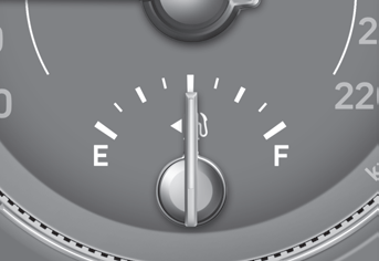
This gauge indicates the approximate amount of fuel remaining in the fuel tank.
Information
The fuel tank capacity is given in chapter 2.
The fuel gauge is supplemented by a low fuel warning light, which will
illuminate when the fuel tank is nearly empty.
On inclines or curves, the fuel gauge pointer may fluctuate or the low
fuel warning light may come on earlier than usual due to the movement of fuel
in the tank.
read more
 MDPS Assembly. Repair procedures
 Restraint


