Hyundai Venue: Seat Electrical / Seat Heater Switch. Schematic diagrams

Hyundai Venue (QX) (2020-2024) Service Manual / Body Electrical System / Seat Electrical / Seat Heater Switch. Schematic diagrams

Circuit Diagram
[Front Seat Heater Switch (Driver)]

Hyundai Venue. Seat Heater Switch. Schematic diagrams

Hyundai Venue. Seat Heater Switch. Schematic diagrams

    Seat Heater Switch. Components and components location

    ..

    Seat Heater Switch. Repair procedures

    Removal [Front Seat] 1. Disconnect the negative (-) battery terminal. 2. Remove the floor console upper cover...

    Other information:

    Hyundai Venue (QX) (2020-2024) Owners Manual: Air bag inflation conditions


    Front air bags Front air bags are designed to inflate in a frontal collision depending on the severity of impact of the front collision. Side and curtain air bags Side and curtain air bags are designed to inflate when an impact is detected by side collision sensors depending on the severity of impact resulting from a side impact collision...

    Hyundai Venue (QX) (2020-2024) Service Manual: Transaxle Control Module (TCM). Schematic diagrams


    TCM Connector Connector [A] Pin Description 2 35R clutch control solenoid valve (35R/C_VFS) 4 26 brake control solenoid valve (26/B_VFS) 5 Underdrive brake control solenoid valve (UD/B_VFS) 8 Inhibitor switch signal S2 (R) 19 Line pressure control solenoid valve (LINE_VFS) 21 Input speed sensor power 22 Output speed sensor power 32 Torque converter control solenoid valve (T/CON_VFS) 33 VB (Battery voltage) 34 Solenoid supply power 2 37 Output speed sensor signal 38 Inhibitor switch signal S4 (D) 39 Inhibitor switch signal S1 (P) 40 Manual mode up shift 42 Manual mode select switch 43 Oil temperature sensor (+) 45 VB (Battery voltage) 46 ON/OFF solenoid valve A(SS-A) 47 Overdrive clutch control solenoid valve (OD/C_VFS) 48 VB (Battery voltage) 49 Solenoid supply power 1 52 Input speed sensor signal 54 Inhibitor switch signal S3 (N) 57 Manual mode down shift 58 Oil temperature sensor (-) TCM Terminal input/ output signal Connector [A] Pin Description Condition Input/output value Type Level 2 35R clutch control solenoid valve (35R/C_VFS) - Output 0V/Battery voltage level 9V < Battery voltage level < 16V 4 26 brake control solenoid valve (26/B_VFS) - Output 0V/Battery voltage level 9V < Battery voltage level < 16V 5 Underdrive brake control solenoid valve (UD/B_VFS) - Output 0V/Battery voltage level 9V < Battery voltage level < 16V 8 Inhibitor switch signal S2 (R) High Input 0V/Battery voltage level Low 9V < Battery voltage level < 16V 19 Line pressure control solenoid valve (LINE_VFS) - Output 0V/Battery voltage level 9V < Battery voltage level < 16V 21 Input speed sensor power ON Power 0V/9V OFF 22 Output speed sensor power ON Power 0V/9V OFF 32 Torque converter control solenoid valve (T/CON_VFS) - Output 0V/Battery voltage level 9V < Battery voltage level < 16V 34 Solenoid power 2 Power 0V/Battery voltage level 9V < Battery voltage level < 16V 37 Output speed sensor signal High Input 0...

    Categories

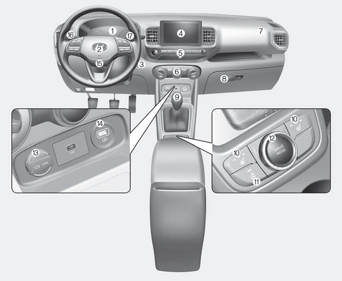
    Instrument Panel Overview

    Hyundai Venue. Instrument Panel Overview

    1. Instrument cluster
    2. Horn
    3. Key ignition switch/ Engine Start/Stop button
    4. Infotainment system
    5. Hazard warning flasher switch

    read more


    Copyright © 2024 www.hvenueqx.com