Hyundai Venue (QX): Stop Lamp Switch / Repair procedures
| Adjustment |
| 1. |
Turn ignition switch OFF and disconnect the negative (-) battery cable.
|
| 2. |
Remove the lower crash pad.
(Refer to Body - "Crash Pad")
|
| 3. |
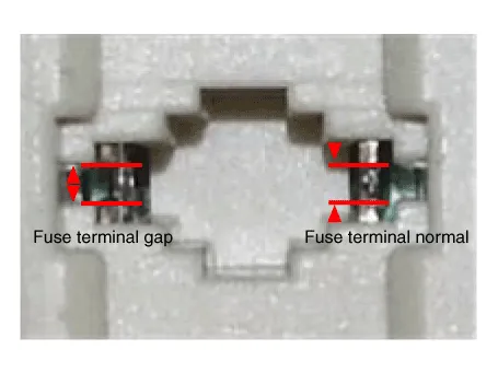
Confirm the gap between stop lamp switch and bracket.
|

| 4. |
If the gap between stop lamp switch and bracket is not 1.0-2.0mm (0.04-0.08in),
check the mounting clip and other part of around stop lamp.
|
| 5. |
If there is normal, remove the stop lamp switch and then install again.
|
| Inspection |
| 1. |
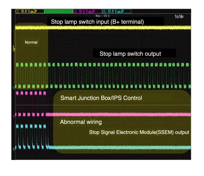
Analyze GDS data and confirm if there is anything wrong with the stop
lamp switch.
|

| Removal |
| 1. |
Turn ignition switch OFF and disconnect the negative (-) battery cable.
|
| 2. |
Remove the crash pad lower panel.
(Refer to Body - "Crash Pad Lower Panel")
|
| 3. |
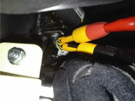
Disconnect the stop lamp switch connector (A).
|

| 4. |
Pull the locking plate (A) as indicated by the arrow.
|

| 5. |
Turn stop lamp switch 45° counterclockwise and remove it.
|

| 6. |
Inspect a removed stop lamp switch along the below procedures.
|

| Installation |
| 1. |
Fix the brake pedal arm and insert fully the stop lamp switch as hiding
contact part.
|

| 2. |
After inserting, turn the stop switch (A) 45° clockwise, and then assemble
locking plate by pushing.
|

| 3. |
Confirm the gap between stop lamp switch and bracket.
|


| 4. |
Connect the stop lamp switch connector.
|

| 5. |
Install the crash pad lower panel.
(Refer to Body - "Crash Pad Lower Panel")
|
Components 1. Brake member assembly 2. Stop lamp switch 3. Brake pedal arm assembly 4. Brake pedal pad
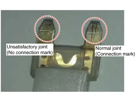
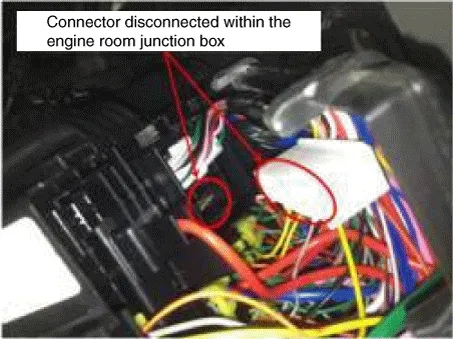
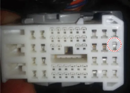
Troubleshooting 1. Part diagnosis Items Cause Symptom Switch fuse Faulty fuse connection, Damaged fuse – DTC Code : P0504 – Symptom : Shifting gear trouble, Starting failure, Cruise control function cancelation trouble, EPB function cancelation trouble, Stop lamp lighting trouble, ESP OFF light illuminated.
Other information:
Hyundai Venue (QX) (2020-2026) Service Manual: Condenser. Repair procedures
Inspection 1. Check the condenser fins for clogging and damage. If clogged, clean them with water, and blow them with compressed air. If bent, gently bend them using a screwdriver or pliers. 2.
Hyundai Venue (QX) (2020-2026) Service Manual: Heater Core. Repair procedures
Replacement 1. Remove the heater unit assembly. (Refer to Heater - "Heater Unit") 2. Loosen the mounting screws and remove the heater core cover (A). 3.
Categories
- Manuals Home
- Hyundai Venue Owners Manual
- Hyundai Venue Service Manual
- Normal Maintenance Schedule
- Rear Seat Assembly. Repair procedures
- Engine Mechanical System
- New on site
- Most important about car
