Hyundai Venue (QX): Forward Collision-Avoidance Assist (FCA) System-Sensor Fusion / FCA Warning Message and System Control
FCA produces warning messages and warning alarms in accordance with the collision risk levels, such as abrupt stopping of the vehicle in front, insufficient braking distance, or pedestrian detection. Also, it controls the brakes in accordance with the collision risk levels.
Collision Warning (First warning)
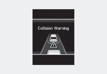
This warning message appears on the LCD display with a warning chime. Additionally, some vehicle system intervention occurs by the engine management system to help decelerate the vehicle.
-- Your vehicle speed may decelerate moderately.
-- FCA system limitedly controls the brakes to preemptively mitigate impact in a
collision.
-- If you select ŌĆśWarning onlyŌĆÖ, FCA system activates and produces only warning
alarms in accordance with the collision risk levels. You should control the brakes
directly because The FCA system will not control the brakes.
Emergency Braking (Second warning)
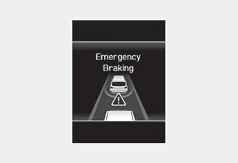
This warning message appears on the LCD display with a warning chime.
Additionally, some vehicle system intervention occurs by the engine management system to help decelerate the vehicle.
-- FCA system limitedly controls the brakes to preemptively mitigate impact in
a collision. The brake control is maximized just before a collision.
-- If you select ŌĆśWarning onlyŌĆÖ, FCA system activates and produces only warning
alarms in accordance with the collision risk levels. You should control the brakes
directly because The FCA system will not control the brakes.
Brake operation
- In an urgent situation, the braking system enters into the ready status for prompt reaction against the driverŌĆÖs depressing the brake pedal.
- FCA provides additional braking power for optimum braking performance, when the driver depresses the brake pedal.
- The braking control is automatically deactivated, when the driver sharply depresses the accelerator pedal, or when the driver abruptly operates the steering wheel.
- FCA braking control is automatically canceled, when risk factors disappear.
CAUTION
The driver should always use extreme caution while operating the vehicle, whether or not there is a warning message or alarm from FCA system.
- After the brake control is activated, the driver must immediately depress the brake pedal and check the surroundings. The brake activation by the system lasts for about 2 seconds.
- If any other warning sound such as seat belt warning chime is already generated, Forward Collision- Avoidance Assist (FCA) system warning may not sound.
- Playing the vehicle audio system at high volume may prevent occupants from hearing the system warning sounds.
WARNING
The FCA braking control cannot completely stop the vehicle nor avoid all collisions. The driver should hold the responsibility to safely drive and control the vehicle.
WARNING
FCA system logic operates within certain parameters, such as the distance from the vehicle or pedestrian ahead, the speed of the vehicle ahead, and the driver's vehicle speed. Certain conditions such as inclement weather and road conditions may affect the operation of FCA system.
WARNING
Never deliberately drive dangerously to activate the system.
System setting ŌĆó Setting Forward Safety function The driver can activate FCA by placing the ignition switch to the ON position and by selecting: ŌĆśUser Settings ŌåÆ Driver Assistance ŌåÆ Forward SafetyŌĆÖ -- If you select ŌĆ£Active AssistŌĆØ, FCA system activates.
Front view camera Front radar In order for FCA system to operate properly, always make sure the sensor cover or sensor is clean and free of dirt, snow, and debris.
Other information:
Hyundai Venue (QX) (2020-2026) Service Manual: Condenser. Repair procedures
Inspection 1. Check the condenser fins for clogging and damage. If clogged, clean them with water, and blow them with compressed air. If bent, gently bend them using a screwdriver or pliers. 2.
Hyundai Venue (QX) (2020-2026) Service Manual: Heater & A/C Control Unit (Manual). Repair procedures
Replacement 1. Disconnect the negative (-) battery terminal. 2. Remove the console upper front garnish. (Refer to Floor Console - "Floor Console Assembly") 3.
Categories
- Manuals Home
- Hyundai Venue Owners Manual
- Hyundai Venue Service Manual
- Body (Interior and Exterior)
- Automatic Transaxle Fluid (ATF). Repair procedures
- Remote start
- New on site
- Most important about car
