Hyundai Venue: While Driving / Cruise Control

Hyundai Venue (QX) (2020-2024) Owners Manual / While Driving / Cruise Control

Cruise Control Operation

Hyundai Venue. Cruise Control

1. Cruise indicator
2. SET indicator

The Cruise Control system allows you to drive at speeds above 20 MPH (30 km/h) without depressing the accelerator pedal.

WARNING

Take the following precautions:

  • Always set the vehicle speed under the speed limit.
  • If the Cruise Control is left on, (cruise indicator light in the instrument cluster is illuminated) the Cruise Control can be activated unintentionally. Keep the Cruise Control system off (cruise indicator light OFF) when the Cruise Control is not in use, to avoid inadvertently setting a speed.
  • Use the Cruise Control system only when traveling on open highways in good weather.
  • Do not use the Cruise Control when it may be unsafe to keep the vehicle at a constant speed.

• Do not use when:

-- Driving in heavy traffic or when traffic conditions make it difficult to drive at a constant speed
-- Driving on rainy, icy, or snowcovered roads
-- Driving on hilly or windy roads
-- Driving in windy areas
-- Driving with limited view (possibly due to bad weather such as fog, snow, rain and sandstorm)

Information

  • During normal cruise control operation, when the SET switch is activated or reactivated after applying the brakes, the cruise control will energize after approximately 3 seconds. This delay is normal.
  • Before activating the cruise control function, the system will check to verify that the brake switch is operating normally. Depress the brake pedal at least once after turning ON the ignition or starting the engine.

Leading vehicle departure alert

Leading Vehicle Departure Alert function provides the alert whether the leading vehicle drives away or not, while a stop. System setting and operating Conditions • Selecting Driver Attention Warning Leading Vehicle Departure Alert can be activated from Users mode in the cluster LCD display by following the procedure below...

To set Cruise Control speed

1. Press the CRUISE button on the steering wheel to turn the system on. The cruise indicator will illuminate. 2. Accelerate to the desired speed, which must be more than 20 MPH (30 km/h)...

Other information:

Hyundai Venue (QX) (2020-2024) Service Manual: Specifications


Specifications Item Specifications Working voltage DC 12.5V ± 0.3V Operating force Initial position : 0.25 ± 0.15N(0.025 ± 0.015kg, 0.056 ± 0.034lb) Full position : 0...

Hyundai Venue (QX) (2020-2024) Service Manual: Engine Control Module (ECM). Schematic diagrams


Engine Control Module (ECM) [M/T] ECM Terminal Function [M/T] Connector [A] Pin No Description Connected to 1 Injector (Cylinder #1) control output Injector (Cylinder #1) 2 Sensor power (+5V) Throttle Position Sensor (TPS) # 1, 2 [ETC module] 3 Sensor power (+5V) Accelerator Position Sensor (APS) 1 4 Main Relay control output Main Relay 5 - - 6 Alternator signal input [FR] Alternator 7 Engine coolant temperature sensor (ECTS) signal input Engine coolant temperature sensor (ECTS) 8 Sensor ground Manifold absolute pressure sensor (MAPS) 9 - 10 Sensor ground Heated Oxygen Sensor (HO2S) [Bank 1 / Sensor 2] 11 - 12 - 13 CVVT Oil Control (OCV) Valve [Bank 1/Intake] control output CVVT Oil Control Valve (OCV) [Bank 1 / Intake] 14 Sensor power (+5V) Manifold absolute pressure sensor (MAPS) 15 Sensor power (+5V) Accelerator Position Sensor (APS) #2 A/C Pressure Transducer (APT) 16 Sensor power (+5V) CMPS [Bank 1 / Intake] CMPS [Bank 1 / Exhaust] 17 Vehicle speed signal input ABS/ESP Control Module [With ABS / ESP] 18 Battery voltage supply after ignition switch Ignition Switch 19 Sensor ground Camshaft Position Sensor (CMPS) [Bank 1 / Exhaust] 20 Sensor ground A/C Pressure Transducer (APT) 21 Sensor ground Battery sensor 22 - 23 - 24 - 25 Injector (Cylinder #2) control output Injector (Cylinder #2) 26 Cooling Fan Relay [High] control output Cooling Fan Relay [High] 27 Start relay control output (With smart key) Start relay 28 Alternator control output [COM] Alternator 29 C-CAN [Low] Other control module, Data Link Connector (DLC), 30 - 31 Camshaft Position Sensor (CMPS) [Bank 1 / Exhaust] signal input Camshaft Position Sensor (CMPS) [Bank 1 / Exhaust] 32 Sensor ground Crankshaft Position Sensor (CKPS) 33 Crankshaft Position Sensor (CKPS) signal input Crankshaft Position Sensor (CKPS) 34 Sensor ground Throttle Position Sensor (TPS) 1, 2 35 Sensor ground Accelerator Position Sensor (APS) 2 36 Sensor ground Accelerator Position Sensor (APS) 1 37 Injector (Cylinder #4) control output Injector (Cylinder #4) 38 - 39 Engine RPM signal output Smart key Control Module 40 Immobilizer communication line Immobilizer Control module [Without Smart Key] Smart Key Control module [With Smart Key] 41 C-CAN [High] Other control module, Data Link Connector (DLC) 42 - 43 Purge Control Solenoid Valve control output Purge Control Solenoid Valve (PCSV) 44 - 45 Injector (Cylinder #3) control output Injector (Cylinder #3) 46 Cooling Fan Relay [Low] control output Cooling Fan Relay [Low] 47 Camshaft Position Sensor (CMPS) [Bank 1 / Intake] signal input haft Position Sensor (CMPS) [Bank 1 / Intake] 48 Battery power (B+) Battery 49 Heated Oxygen Sensor [Bank 1 / Sensor 1] Heater control output Heated Oxygen Sensor [Bank 1 / Sensor 1] 50 Power Ground Chassis Ground 51 - 52 Power Ground Chassis Ground 53 Heated Oxygen Sensor [Bank 1 / Sensor 2] Heater control output Heated Oxygen Sensor [Bank 1 / Sensor 2] 54 CVVT Oil Control (OCV) Valve [Bank 1 / Exhaust] control output CVVT Oil Control Valve (OCV) [Bank 1 / Exhaust] 55 Battery voltage supply after main relay Main relay 56 Battery voltage supply after main relay Main relay Connector [B] Pin No Description Connected to 1 Sensor ground Engine Coolant Temperature Sensor (ECTS) 2 Throttle position sensor (TPS) #2 signal input Throttle position sensor (TPS) #2 [ETC Module] 3 Manifold absolute pressure sensor (MAPS) signal input Manifold absolute pressure sensor (MAPS) 4 A/C Pressure Transducer (APT) signal input A/C Pressure Transducer (APT) 5 - 6 - 7 Accelerator Position Sensor (APS) #1 signal input Accelerator Position Sensor (APS) #1 8 - 9 - 10 - 11 Electric Load signal input (Defrost) A/C Control Module, Outside Mirror 12 Brake switch 1 signal input Brake lamp swtich , Brake switch 13 Heated Oxygen Sensor [Bank 1 / Sensor 2] signal input Heated Oxygen Sensor [Bank 1 / Sensor 2] 14 Battery Sensor Temperature signal input Battery sensor 15 Intake air temperature sensor (IATS) signal input Intake Air temperature sensor (IATS) 16 Battery Sensor Current Direct signal input Battery sensor 17 - 18 Accelerator Position Sensor (APS) #2 signal input Accelerator Position Sensor (APS) #2 19 - 20 - 21 - 22 Throttle position sensor (TPS) #1 signal input Throttle position sensor (TPS) #1 23 Brake Lamp Switch signal input Brake Switch 24 Start switch signal input Ignition switch 25 Sensor ground Heated Oxygen Sensor [Bank 1 / Sensor 1] 26 - 27 Sensor ground Knock sensor (KS) 28 - 29 Wheel speed sensor [B] signal input Front wheel speed sensor (RH) [Without ABS] 30 Wheel speed sensor [A] signal input Front wheel speed sensor (RH) [Without ABS] 31 - 32 Sensor ground Camshaft Position Sensor (CMPS) [Bank 1 / Intake] Camshaft Position Sensor (CMPS) [Bank 1 / Exhaust] 33 Power Ground Chassis Ground 34 Clutch Switch signal input Clutch switch [M...

Categories

Master warning mode

Hyundai Venue. Master warning mode

This warning light informs the driver the following situations.

-- Forward Collision-Avoidance Assist system malfunction (if equipped)
-- Forward Collision-Avoidance Assist radar blocked (if equipped)
-- Blind-Spot Collision Warning system malfunction (if equipped)
-- Blind-Spot Collision Warning radar blocked (if equipped)
-- Lamp malfunction (if equipped)
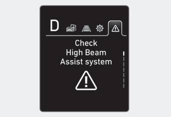
-- High Beam Assist malfunction (if equipped)
-- Tire Pressure Monitoring System (TPMS) malfunction (if equipped)

read more


Copyright © 2024 www.hvenueqx.com