Hyundai Venue: Manual Transaxle Control System / Control Cable. Repair procedures
Hyundai Venue (QX) (2020-2025) Service Manual / Manual Transaxle System / Manual Transaxle Control System / Control Cable. Repair procedures
| Removal |
| 1. |
Turn OFF ignition switch and disconnect the negative (-) battery cable.
|
| 2. |
Remove the air cleaner and air duct.
|
| 3. |
Remove the battery (+) terminal (A).
|
| 4. |
Remove the battery mounting bracket (A) and the battery (B).
|
| 5. |
Remove the ECM.
|
| 6. |
Remove the battery tray.
|
| 7. |
Separate the control cable.
|
| 8. |
Remove the shift knob & boot (A).
|
| 9. |
Remove the floor console assembly.
(Refer to Body - "Floor Console")
|
| 10. |
Separate the clip (A) of wiring.
|
| 11. |
Separate the air duct (A) from the both side.
|
| 12. |
Separate the select cable (B), after removing the snap pin (A).
|
| 13. |
Remove the cable socket (A) from the shift lever, after release the
lock.
|
| 14. |
Remove the shift lever.
|
| 15. |
Loosen the nuts (A) and then removing the retainer (B).
|
| 16. |
Remove the control cable assembly (A) from the vehicle.
|
| Installation |
|
| 1. |
Install the retainer (B) and then tighten the nuts (A).
|
| 2. |
Install the shift cable end (A) and the shift lever (B).
|
| 3. |
Install the shift cable (A) from the shift lever.
|
| 4. |
Install the select cable (B) and the snap pin (A).
|
| 5. |
Install the air duct (A).
|
| 6. |
Install the clip (A) of wiring.
|
| 7. |
Move the locker (B) in the direction of "F" with pulling the holder
(A) in the direction of "P".
|
| 8. |
Install the control cable.
|
| 9. |
Tighten the holder (A) to the "P" directions after fixing the rockers
(B) in the "F" direction.
|
| 10. |
Remove the shift lever 4th fixing pin (A).
|
| 11. |
Install the floor console assembly.
(Refer to Body - "Floor Console")
|
| 12. |
Install the battery tray.
|
| 13. |
Install the ECM.
|
| 14. |
Install the battery (B) and mounting bracket (A).
|
| 15. |
Install the battery (+) terminal (A).
|
| 16. |
Connect the battery (-) cable.
|
 Control Cable. Components and components location
Components
1. Shift lever knob & boots
2. Shift lever assembly
3. Select cable
4. Shift cable
5. Retainer
6...
Other information:
Hyundai Venue (QX) (2020-2025) Owners Manual: While Driving
WARNING Carbon monoxide (CO) gas is toxic. Breathing CO can cause unconsciousness and death. Engine exhaust contains carbon monoxide which cannot be seen or smelled. Do not inhale engine exhaust. If at any time you smell engine exhaust inside the vehicle, open the windows immediately...
Hyundai Venue (QX) (2020-2025) Service Manual: Mode Control Actuator. Components and components location
..
Categories
- Manuals Home
- 1st Generation Venue Owners Manual
- 1st Generation Venue Service Manual
- Trip Computer
- Lighting control
- Rear Combination Light Bulb Replacement
- New on site
- Most important about car
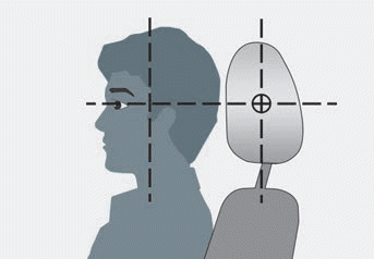
Head Restraints
The vehicle’s front and rear seats have adjustable head restraints. The head restraints provide comfort for passengers, but more importantly they are designed to help protect passengers from whiplash and other neck and spinal injuries during an accident, especially in a rear impact collision.
WARNING
To reduce the risk of serious injury or death in an accident, take the following precautions when adjusting your head restraints:
Always properly adjust the head restraints for all passengers BEFORE starting the vehicle. NEVER let anyone ride in a seat with the head restraints removed or reversed.
Copyright © 2025 www.hvenueqx.com


