Hyundai Venue: Tires and Wheels / Check Tire Inflation Pressure

Hyundai Venue (QX) (2020-2024) Owners Manual / Maintenance / Tires and Wheels / Check Tire Inflation Pressure

Check your tires, including the spare tire, once a month or more.

How to check

Use a good quality tire pressure gauge to check tire pressure. You can not tell if your tires are properly inflated simply by looking at them. Radial tires may look properly inflated when they are underinflated.

Remove the valve cap from the tire valve stem. Press the tire gauge firmly onto the valve to get a pressure measurement. If the cold tire inflation pressure matches the recommended pressure on the tire label located on the driver’s side center pillar or in this manual. No further adjustment is necessary. If the pressure is low, add air until you reach the recommended pressure. Make sure to put the valve caps back on the valve stems. Without the valve cap, dirt or moisture could get into the valve core and cause air leakage. If a valve cap is missing, install a new one as soon as possible.

If you overfill the tire, release air by pushing on the metal stem in the center of the tire valve. Recheck the tire pressure with the tire gauge. Be sure to put the valve caps back on the valve stems. Without the valve cap, dirt or moisture could get into the valve core and cause air leakage. If a valve cap is missing, install a new one as soon as possible.

A cold tire means the vehicle has been sitting for 3 hours and driven for less than 1 mile (1.6 km) in that 3 hour period.

Allow the tire to cool before measuring the inflation pressure. Always be sure the tire is cold before inflating to the recommended pressure.

    Recommended Cold Tire Inflation Pressures

    All tire pressures (including the spare) should be checked when the tires are cold. “Cold tires” means the vehicle has not been driven for at least three hours or has been driven for less than one mile (1...

    Tire Rotation

    To equalize tread wear, HYUNDAI recommends that the tires be rotated according to the maintenance schedule or sooner if irregular wear develops. During rotation, check the tires for correct balance...

    Other information:

    Hyundai Venue (QX) (2020-2024) Service Manual: Front Seat Assembly. Components and components location


    ..

    Hyundai Venue (QX) (2020-2024) Service Manual: Engine Control Module (ECM). Schematic diagrams


    Engine Control Module (ECM) [M/T] ECM Terminal Function [M/T] Connector [A] Pin No Description Connected to 1 Injector (Cylinder #1) control output Injector (Cylinder #1) 2 Sensor power (+5V) Throttle Position Sensor (TPS) # 1, 2 [ETC module] 3 Sensor power (+5V) Accelerator Position Sensor (APS) 1 4 Main Relay control output Main Relay 5 - - 6 Alternator signal input [FR] Alternator 7 Engine coolant temperature sensor (ECTS) signal input Engine coolant temperature sensor (ECTS) 8 Sensor ground Manifold absolute pressure sensor (MAPS) 9 - 10 Sensor ground Heated Oxygen Sensor (HO2S) [Bank 1 / Sensor 2] 11 - 12 - 13 CVVT Oil Control (OCV) Valve [Bank 1/Intake] control output CVVT Oil Control Valve (OCV) [Bank 1 / Intake] 14 Sensor power (+5V) Manifold absolute pressure sensor (MAPS) 15 Sensor power (+5V) Accelerator Position Sensor (APS) #2 A/C Pressure Transducer (APT) 16 Sensor power (+5V) CMPS [Bank 1 / Intake] CMPS [Bank 1 / Exhaust] 17 Vehicle speed signal input ABS/ESP Control Module [With ABS / ESP] 18 Battery voltage supply after ignition switch Ignition Switch 19 Sensor ground Camshaft Position Sensor (CMPS) [Bank 1 / Exhaust] 20 Sensor ground A/C Pressure Transducer (APT) 21 Sensor ground Battery sensor 22 - 23 - 24 - 25 Injector (Cylinder #2) control output Injector (Cylinder #2) 26 Cooling Fan Relay [High] control output Cooling Fan Relay [High] 27 Start relay control output (With smart key) Start relay 28 Alternator control output [COM] Alternator 29 C-CAN [Low] Other control module, Data Link Connector (DLC), 30 - 31 Camshaft Position Sensor (CMPS) [Bank 1 / Exhaust] signal input Camshaft Position Sensor (CMPS) [Bank 1 / Exhaust] 32 Sensor ground Crankshaft Position Sensor (CKPS) 33 Crankshaft Position Sensor (CKPS) signal input Crankshaft Position Sensor (CKPS) 34 Sensor ground Throttle Position Sensor (TPS) 1, 2 35 Sensor ground Accelerator Position Sensor (APS) 2 36 Sensor ground Accelerator Position Sensor (APS) 1 37 Injector (Cylinder #4) control output Injector (Cylinder #4) 38 - 39 Engine RPM signal output Smart key Control Module 40 Immobilizer communication line Immobilizer Control module [Without Smart Key] Smart Key Control module [With Smart Key] 41 C-CAN [High] Other control module, Data Link Connector (DLC) 42 - 43 Purge Control Solenoid Valve control output Purge Control Solenoid Valve (PCSV) 44 - 45 Injector (Cylinder #3) control output Injector (Cylinder #3) 46 Cooling Fan Relay [Low] control output Cooling Fan Relay [Low] 47 Camshaft Position Sensor (CMPS) [Bank 1 / Intake] signal input haft Position Sensor (CMPS) [Bank 1 / Intake] 48 Battery power (B+) Battery 49 Heated Oxygen Sensor [Bank 1 / Sensor 1] Heater control output Heated Oxygen Sensor [Bank 1 / Sensor 1] 50 Power Ground Chassis Ground 51 - 52 Power Ground Chassis Ground 53 Heated Oxygen Sensor [Bank 1 / Sensor 2] Heater control output Heated Oxygen Sensor [Bank 1 / Sensor 2] 54 CVVT Oil Control (OCV) Valve [Bank 1 / Exhaust] control output CVVT Oil Control Valve (OCV) [Bank 1 / Exhaust] 55 Battery voltage supply after main relay Main relay 56 Battery voltage supply after main relay Main relay Connector [B] Pin No Description Connected to 1 Sensor ground Engine Coolant Temperature Sensor (ECTS) 2 Throttle position sensor (TPS) #2 signal input Throttle position sensor (TPS) #2 [ETC Module] 3 Manifold absolute pressure sensor (MAPS) signal input Manifold absolute pressure sensor (MAPS) 4 A/C Pressure Transducer (APT) signal input A/C Pressure Transducer (APT) 5 - 6 - 7 Accelerator Position Sensor (APS) #1 signal input Accelerator Position Sensor (APS) #1 8 - 9 - 10 - 11 Electric Load signal input (Defrost) A/C Control Module, Outside Mirror 12 Brake switch 1 signal input Brake lamp swtich , Brake switch 13 Heated Oxygen Sensor [Bank 1 / Sensor 2] signal input Heated Oxygen Sensor [Bank 1 / Sensor 2] 14 Battery Sensor Temperature signal input Battery sensor 15 Intake air temperature sensor (IATS) signal input Intake Air temperature sensor (IATS) 16 Battery Sensor Current Direct signal input Battery sensor 17 - 18 Accelerator Position Sensor (APS) #2 signal input Accelerator Position Sensor (APS) #2 19 - 20 - 21 - 22 Throttle position sensor (TPS) #1 signal input Throttle position sensor (TPS) #1 23 Brake Lamp Switch signal input Brake Switch 24 Start switch signal input Ignition switch 25 Sensor ground Heated Oxygen Sensor [Bank 1 / Sensor 1] 26 - 27 Sensor ground Knock sensor (KS) 28 - 29 Wheel speed sensor [B] signal input Front wheel speed sensor (RH) [Without ABS] 30 Wheel speed sensor [A] signal input Front wheel speed sensor (RH) [Without ABS] 31 - 32 Sensor ground Camshaft Position Sensor (CMPS) [Bank 1 / Intake] Camshaft Position Sensor (CMPS) [Bank 1 / Exhaust] 33 Power Ground Chassis Ground 34 Clutch Switch signal input Clutch switch [M...

    Categories

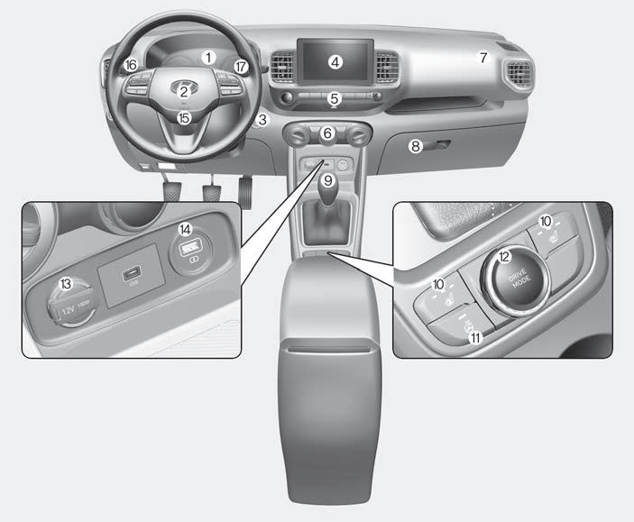
    Instrument Panel Overview

    Hyundai Venue. Instrument Panel Overview

    1. Instrument cluster
    2. Horn
    3. Key ignition switch/ Engine Start/Stop button
    4. Infotainment system
    5. Hazard warning flasher switch

    read more


    Copyright © 2024 www.hvenueqx.com