Hyundai Venue: Automatic Transaxle Control System / Transaxle Control Module (TCM). Repair procedures
Hyundai Venue (QX) (2020-2025) Service Manual / Automatic Transaxle System / Automatic Transaxle Control System / Transaxle Control Module (TCM). Repair procedures
| Inspection |
▶ Transaxle Control Module(TCM) Problem Inspection Procedure
| 1. |
TEST TCM GROUND CIRCUIT: Measure resistance between TCM and chassis
ground using the backside of TCM harness connector as TCM side check
point. If the problem is found, repair it.
|
| 2. |
TEST TCM CONNECTOR: Disconnect the TCM connector and visually check
the ground terminals on TCM side and harness side for bent pins or poor
contact pressure. If the problem is found, repair it.
|
| 3. |
If problem is not found in Step 1 and 2, the TCM could be faulty. If
so, make sure there were no DTC's before swapping the TCM with a new
one, and then check the vehicle again. If DTC's were found, examine
this first before swapping TCM.
|
| 4. |
RE-TEST THE ORIGINAL TCM: Install the original TCM (may be broken) into
a known-good vehicle and check the vehicle. If the problem occurs again,
replace the original TCM with a new one. If problem does not occur,
this is intermittent problem (Refer to “Intermittent Problem Inspection
Procedure” in Basic Inspection Procedure).
|
| Removal |
| 1. |
Perform the oil pressure characteristics backup procedure using the
diagnostic tool when replacing with a new TCM.
|
| 2. |
Turn ignition switch OFF.
|
| 3. |
Disconnect the battery (-) terminal (A).
|
| 4. |
Disconnect the battery (+) terminal (B).
|
| 5. |
Remove the battery mounting bracket (A) and the battery (B).
|
| 6. |
Disconnect the TCM connector (A).
|
| 7. |
Remove the bolts (A) and nut (B).
|
| 8. |
Remove the TCM (C).
|
| Installation |
| 1. |
To install, reverse the removal procedure.
|
| 2. |
Oil-pressure characteristics input (TCM exchange)
|
| 3. |
Perform the procedures related in the ECM after replacing the TCM.
(Refer to Engine Control / Fuel System - "Engine Control Module")
|
| 4. |
Perform TCM learning after replacing the transaxle to prevent slow transaxle
response, jerky acceleration and jerky startup.
(Refer to Automatic Transaxle Control System - "Repair procedures")
|
 Transaxle Control Module (TCM). Schematic diagrams
TCM Connector
Connector [A]
Pin
Description
2
35R clutch control solenoid valve (35R/C_VFS)
4
26 brake control solenoid valve (26/B_VFS)
5
Underdrive brake control solenoid valve (UD/B_VFS)
8
Inhibitor switch signal S2 (R)
19
Line pressure control solenoid valve (LINE_VFS)
21
Input speed sensor power
22
Output speed sensor power
32
Torque converter control solenoid valve (T/CON_VFS)
33
VB (Battery voltage)
34
Solenoid supply power 2
37
Output speed sensor signal
38
Inhibitor switch signal S4 (D)
39
Inhibitor switch signal S1 (P)
40
Manual mode up shift
42
Manual mode select switch
43
Oil temperature sensor (+)
45
VB (Battery voltage)
46
ON/OFF solenoid valve A(SS-A)
47
Overdrive clutch control solenoid valve (OD/C_VFS)
48
VB (Battery voltage)
49
Solenoid supply power 1
52
Input speed sensor signal
54
Inhibitor switch signal S3 (N)
57
Manual mode down shift
58
Oil temperature sensor (-)
TCM Terminal input/ output signal
Connector [A]
Pin
Description
Condition
Input/output value
Type
Level
2
35R clutch control solenoid valve
(35R/C_VFS)
-
Output
0V/Battery voltage level
9V < Battery voltage level < 16V
4
26 brake control solenoid valve
(26/B_VFS)
-
Output
0V/Battery voltage level
9V < Battery voltage level < 16V
5
Underdrive brake control solenoid valve
(UD/B_VFS)
-
Output
0V/Battery voltage level
9V < Battery voltage level < 16V
8
Inhibitor switch signal S2 (R)
High
Input
0V/Battery voltage level
Low
9V < Battery voltage level < 16V
19
Line pressure control solenoid valve
(LINE_VFS)
-
Output
0V/Battery voltage level
9V < Battery voltage level < 16V
21
Input speed sensor power
ON
Power
0V/9V
OFF
22
Output speed sensor power
ON
Power
0V/9V
OFF
32
Torque converter control solenoid valve
(T/CON_VFS)
-
Output
0V/Battery voltage level
9V < Battery voltage level < 16V
34
Solenoid power 2
Power
0V/Battery voltage level
9V < Battery voltage level < 16V
37
Output speed sensor signal
High
Input
0...
 Transaxle Oil Temperature Sensor. Description and operation
Description
•
Transaxle oil temperature sensor monitors the automatic transaxle fluid's
temperature and conveys the readings to TCM...
Other information:
Hyundai Venue (QX) (2020-2025) Service Manual: Delivery Pipe. Repair procedures
Removal 1. Release the residual pressure in fuel line. (Refer to Fuel Delivery System - "Release Residual Pressure in Fuel Line") 2. Turn the ignition switch OFF and disconnect the battery negative (-) terminal...
Hyundai Venue (QX) (2020-2025) Service Manual: Sunroof Deflector. Repair procedures
Replacement 1. Open the glass fully. 2. Remove the mounting bolt (C), from the frame (B), and then remove the deflector (A). 3. To install, reverse the removal procedure...
Categories
- Manuals Home
- 1st Generation Venue Owners Manual
- 1st Generation Venue Service Manual
- Smart Key
- Immobilizer System
- Warning and Indicator Lights
- New on site
- Most important about car
Master warning mode

This warning light informs the driver the following situations.
-- Forward Collision-Avoidance Assist system malfunction (if equipped)
-- Forward Collision-Avoidance Assist radar blocked (if equipped)
-- Blind-Spot Collision Warning system malfunction (if equipped)
-- Blind-Spot Collision Warning radar blocked (if equipped)
-- Lamp malfunction (if equipped)
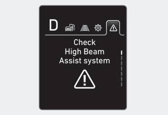
-- High Beam Assist malfunction (if equipped)
-- Tire Pressure Monitoring System (TPMS) malfunction (if equipped)
Copyright © 2025 www.hvenueqx.com


