Hyundai Venue: Timing System / Timing Chain Cover. Repair procedures
Hyundai Venue (QX) (2020-2025) Service Manual / Engine Mechanical System / Timing System / Timing Chain Cover. Repair procedures
| Removal |
|
|
| 1. |
Remove the drive belt.
(Refer to Timing System - "Drive Belt")
|
| 2. |
Remove the drive belt idler.
(Refer to Timing System - "Idler")
|
| 3. |
Remove the alternator.
(Refer to Engine Electrical System - "Alternator")
|
| 4. |
Remove the alternetor bracket.
(Refer to Timing Systme - "Drive Belt Tensioner")
|
| 5. |
Remove the engine room under cover.
|
| 6. |
Remove the crankshaft damper pulley.
(Refer to Timing System - Crankshaft Damper Pulley")
|
| 7. |
Remove the water pump.
(Refer to Cooling System - "Water Pump")
|
| 8. |
Remove the air cleaner assembly.
(Intake and Exhaust System - "Air Cleaner")
|
| 9. |
Remove the cylinder head cover.
(Refer to Cylinder Head Assembly - "Cylinder Head Cover")
|
| 10. |
Remove the engine mounting support bracket.
|
| 11. |
Remove the Engine support bracket (A).
|
| 12. |
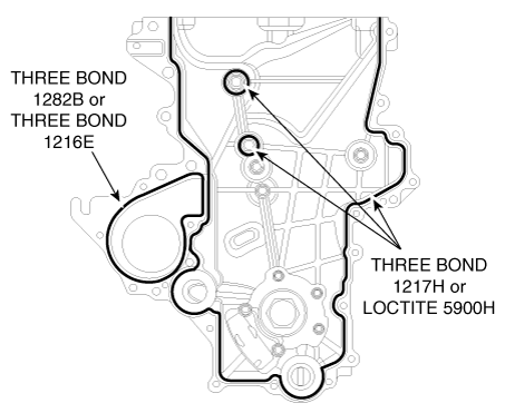
Remove the Timing Chain Cover (A).
|
| Installation |
| 1. |
Install the timing chain cover (A).
|
| 2. |
Install the engine support bracket (A).
|
| 3. |
Installation is reverse order of removal.
|
Other information:
Hyundai Venue (QX) (2020-2025) Service Manual: Transaxle Control Module (TCM). Description and operation
Description • Monitors the vehicle's operating conditions to determine the optimal gear setting. • Performs a gear change if the current gear setting differs from the identified optimal gear setting...
Hyundai Venue (QX) (2020-2025) Service Manual: Troubleshooting
..
Categories
- Manuals Home
- 1st Generation Venue Owners Manual
- 1st Generation Venue Service Manual
- Liftgate
- Vehicle Identification Number (vin), Vehicle Certification Label
- Electronic Stability Control (ESC)
- New on site
- Most important about car
Interior Overview

1. Door lock/unlock button
2. Outside rearview mirror control switch
3. Central door lock switch
4. Power window switches
5. Power window lock switch
Copyright © 2025 www.hvenueqx.com


