Hyundai Venue: Forward Collision-Avoidance Assist (FCA) System / System Malfunction
Hyundai Venue (QX) (2020-2025) Owners Manual / While Driving / Forward Collision-Avoidance Assist (FCA) System / System Malfunction

Check Forward Collision-Avoidance Assist system
- When FCA is not working properly, FCA warning light (
 )
will illuminate and the warning message will appear for a few seconds. After
the message disappears, the master warning light (
)
will illuminate and the warning message will appear for a few seconds. After
the message disappears, the master warning light ( )
will illuminate. In this case, have the vehicle inspected by an authorized HYUNDAI
dealer.
)
will illuminate. In this case, have the vehicle inspected by an authorized HYUNDAI
dealer. - FCA warning message may appear along with the illumination of the ESC (Electronic Stability Control) warning light and FCA is automatically deactivated.
WARNING
- FCA is only a supplemental system for the driver's convenience. The driver should hold the responsibility to control the vehicle operation. Do not solely depend on FCA system. Rather, maintain a safe braking distance, and, if necessary, depress the brake pedal to reduce the driving speed.
- In certain instances and under certain driving conditions, FCA system may activate unintentionally. This initial warning message appears on the LCD display with a warning chime. Also, in certain instances the front view camera recognition system may not detect the vehicle ahead. FCA system may not activate and the warning message will not be displayed.
- If there is a malfunction with FCA system, the Forward Collision avoidance assist system is not applied even though the braking system is operating normally.
- If the vehicle in front stops suddenly, you may have less control of the brake system. Therefore, always keep a safe distance between your vehicle and the vehicle in front of you.
- FCA system may activate during braking and the vehicle may stop suddenly shifting loose objects toward the passengers. Always keep loose objects secured.
- FCA system may not activate if the driver applies the brake pedal to avoid a collision.
- The brake control may be insufficient, possibly causing a collision, if a vehicle in front abruptly stops. Always pay extreme caution. • Occupants may get injured, if the vehicle abruptly stops by activated FCA system. Pay extreme caution.
- Even if there is any problem in FCA system's brake control function, general braking performance will operate normally. In this case, the brake control function which operates when the collision is imminent will not activate.
WARNING
- FCA system operates only to detect vehicles in front of the vehicle.
- FCA system does not operate when the vehicle is in reverse.
- FCA system is not designed to detect other objects on the road such as animals.
- FCA system does not detect vehicles in the opposite lane.
- FCA system does not detect cross traffic vehicles that are approaching.
- FCA system cannot detect the driver approaching the side view of a parked vehicle (for example on a dead end street.)
In these cases, you must maintain a safe braking distance, and if necessary, depress the brake pedal to reduce the driving speed in order to maintain a safe distance.
 FCA Sensor
Front camera
In order for FCA system to operate properly, always make sure the front view
camera is clean and free of dirt, snow, and debris. Dirt, snow, or foreign substances
on the surface may adversely affect the sensing performance of the camera...
 Limitations of the System
Forward Collision-Avoidance Assist system is designed to monitor the vehicle
ahead in the roadway through camera recognition to warn the driver that a collision
is imminent, and if necessary, apply emergency braking...
Other information:
Hyundai Venue (QX) (2020-2025) Owners Manual: Rear seat head restraints
The rear seats are equipped with head restraints in all the seating positions for the passenger’s safety and comfort. CAUTION For each rear passenger, adjust the head restraint so that the middle of the head restraint is at the same height as the height of the top of the eyes...
Hyundai Venue (QX) (2020-2025) Service Manual: Driver Airbag (DAB) Module and Clock Spring. Repair procedures
Removal 1. Disconnect the battery negative cable and wait for at least three minutes before beginning work. 2. Remove the driver airbag module mounting bolts. 3. Disconnect the DAB connector (A)...
Categories
- Manuals Home
- 1st Generation Venue Owners Manual
- 1st Generation Venue Service Manual
- Remote start
- Warning and Indicator Lights
- Type B, C
- New on site
- Most important about car
Interior Overview
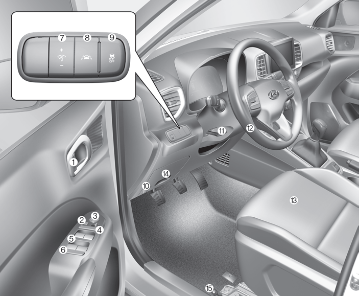
1. Door lock/unlock button
2. Outside rearview mirror control switch
3. Central door lock switch
4. Power window switches
5. Power window lock switch
Copyright © 2025 www.hvenueqx.com