Hyundai Venue: Rear Disc Brake / Repair procedures
| Removal |
| 1. |
Loosen the wheel nuts slightly.
Raise the vehicle, and make sure it is securely supported.
|
| 2. |
Remove the rear wheel and tire (A) from the rear hub.
|
| 3. |
Loosen the brake hose bolt (A) from the caliper seperate the brake hose.
|
| 4. |
Disconnect the parking cable (B) after remove the parking brake cable
fixing clip (A).
|
| 5. |
Remove the caliper body (A) by loosening the guided rod bolt.
|
| 6. |
Remove the pad return spring (A).
|
| 7. |
Remove the brake pad (A).
|
| 8. |
Remove the pad liner (A).
|
| 9. |
Remove the caliper carrier (A) by loosening the caliper mouniting bolts.
|
| 10. |
Remove the rear brake disc (A) by loosening the screws.
|
| Installation |
| 1. |
To install, reverse the removal procedure.
|
| 2. |
When istalling, press and rotate the piston into the caliper body until
it is fully retracted.
|
| 3. |
After installing, bleed the brake system.
(Refer to Brake System - "Brake System Bleeding")
(Refer to Brake System - "ABS System Bleeding")
(Refer to Brake System - "ESP System Bleeding")
|
| Inspection |
Rear Brake Disc Thickness Check
| 1. |
Check the brake disc for damage and cracks.
|
| 2. |
Remove all rust and contamination from the surface, and measure the
disc thickness at 24 points, at least, of same distance (5mm) from the
brake disc outer circle.
|
| 3. |
If wear exceeds the limit, replace the discs and pad assembly left and
right of the vehicle.
|
Rear Brake Disc Runout Check
| 1. |
Place a dial gauge about 10mm (0.2 in.) from the outer circumference
of the brake disc, and measure the runout of the disc.
|
| 2. |
If the runout of the brake disc exceeds the limit specification, replace
the disc, and then measure the runout again.
|
| 3. |
If the runout cannot be corrected by changing the position of the brake
disc, replace the brake disc.
|
| Adjustment |
|
| 1. |
Remove the floor console to reach the adjusting nut.
|
| 2. |
Loosen the parking brake cable until both operating levers rest in fully
off position.
|
| 3. |
Bring the brake pads in their operating position by pressing the brake
pedal down several times until there is resistance.
|
| 4. |
Tension the parking brake cable by tightening the adjusting nut, until
the operating levers on both calipers lift from the stop, up to a distance
of (A) and (D) between operating lever (B) and stopper (C).
|
| 5. |
Refit the floor console.
|
| 6. |
Parking brake lever in the car must be in fully loosened position.
|
| 7. |
If the handbrake cables where changed, actuate the parking brake a few
times with maximum force to stretch the parking brake cables, and then
control adjusting as above.
|
| 8. |
Check the wheels of their free operation.
|
| 9. |
Test drive.
|
 Brake Pad
..
Other information:
Hyundai Venue (QX) (2020-2025) Service Manual: Input Speed Sensor. Repair procedures
Removal • When Diagnostic Trouble Codes (DTC) is on, perform the following procedure to replace it. • Automatic transaxle is composed of delicate components...
Hyundai Venue (QX) (2020-2025) Service Manual: Valve Body. Description and operation
Description The valve body is essential to automatic transaxle control and consists of various valves used to control the oil feed from the oil pump. Specifically, these valves consist of pressure regulator valves, oil redirection valves, shift valves, and manual valves...
Categories
- Manuals Home
- 1st Generation Venue Owners Manual
- 1st Generation Venue Service Manual
- Smart Key
- Remote Key
- Warning and Indicator Lights
- New on site
- Most important about car
Head Restraints
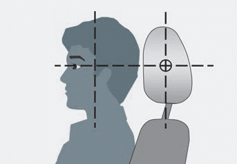
The vehicle’s front and rear seats have adjustable head restraints. The head restraints provide comfort for passengers, but more importantly they are designed to help protect passengers from whiplash and other neck and spinal injuries during an accident, especially in a rear impact collision.
WARNING
To reduce the risk of serious injury or death in an accident, take the following precautions when adjusting your head restraints:
Always properly adjust the head restraints for all passengers BEFORE starting the vehicle. NEVER let anyone ride in a seat with the head restraints removed or reversed.
Copyright © 2025 www.hvenueqx.com


