Hyundai Venue: Lubrication System / Engine Oil. Repair procedures
• |
Prolonged and repeated contact with mineral oil will result
in the removal of natural fats from the skin, leading to dryness,
irritation and dermatitis. In addition, used engine oil contains
potentially harmful contaminants which may cause skin cancer.
|
• |
Exercise caution in order to minimize the length and frequency
of contact of your skin to used oil. Wear protective clothing
and gloves. Wash your skin thoroughly with soap and water, or
use water-less hand cleaner, to remove any used engine oil.
Do not use gasoline, thinners, or solvents.
|
• |
In order to preserve the environment, used oil and used oil
filter must be disposed of only at designated disposal sites.
|
|
1. |
Drain the engine oil.
(1) |
Remove the oil filler cap.
|
(2) |
Remove the oil drain plug, and drain the oil into a container.
|
|
2. |
Remove the oil filter (A) with the SST (09263-2E000, the oil filter
wrench).
(1) |
Remove the oil filter.
|
(2) |
Check and clean the oil filter installation surface.
|
(3) |
Check the part number of the new oil filter is as same as old
one.
|
(4) |
Apply clean engine oil to the gasket of a new oil filter.
|
(5) |
Lightly screw the oil filter into place, and tighten it until
the gasket contacts the seat.
|
(6) |
Tighten it with the torque below.
Tightening torque :
11.8 - 15.7 N.m (1.2 - 1.6 kgf.m, 8.7 - 11.6 lb-ft)
|

|
|
3. |
Refill with engine oil.
(1) |
Clean and install the oil drain plug with a new gasket.
Tightening torque :
34.3 - 44.1 N.m (3.5 - 4.5 kgf.m, 25.3 - 32.5 lb-ft)
|
|
(2) |
Fill with fresh engine oil.
Capacity
Total : 3.7 - 4.0L (3.90 - 4.22 US qt, 3.25 - 3.51 lmp
qt, 0.97 - 1.05 US gal)
Oil pan : 3.3L (3.48US qt, 2.90lmp qt, 0.87 US gal)
Drain and refill in cluding oil filter :
3.6 L (3.80US qt, 3.16lmp qt, 0.95 US gal)
|
|
(3) |
Install the oil filler cap.
|
|
4. |
Start engine and check for oil leaks.
|
5. |
Recheck the engine oil level.
|
Engine Oil
1. |
Check the engine oil quality.
Check the oil deterioration, entry of water, discoloring of thinning.
If the quality is visibly poor, replace the oil.
|
2. |
Check the engine oil level.
After warning up the engine and then 5 minutes after the engine stop,
oil level should be between the "L" and "F" marks in the dipstick.
If low, check for leakage and add oil up to the "F" mark.
•
|
Do not fill with engine oil above the "F" mark.
|
|
|
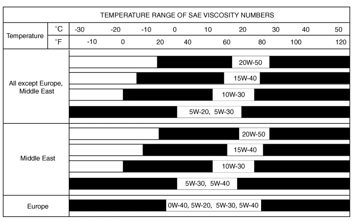
Selection of Engine Oil
Specification
For all except Middle East :
API SM & ILSAC GF-4 or above / 5W-20
ACEA A5 or above / 5W-20
For Middle East :
ACEA A5 or above / 5W-30
• |
API SL, ILSAC GF-3, ACEA A3 Class engine oil can be used if
the recommended engine oil is not available.
|
|
SAE viscosity grade
Refer to the recommended SAE viscosity number.

• |
For best performance and maximum protection of all types of
operation, select only those lubricants which :
|
1) |
Satisfy the requirement of the API, ILSAC or ACEA classification.
|
2) |
Have proper SAE grade number for expected ambient temperature
range.
|
3) |
Lubricants that do not have both an SAE grade number and API,
ILSAC or ACEA service classification on the container should
not be used.
|
|
Removal and Installation
1.
Disconnect the battery negative terminal.
2.
Remove the engine room under cover...
Other information:
Engine Control Module (ECM)
[M/T]
ECM Terminal Function [M/T]
Connector [A]
Pin No
Description
Connected to
1
Injector (Cylinder #1) control output
Injector (Cylinder #1)
2
Sensor power (+5V)
Throttle Position Sensor (TPS) # 1, 2 [ETC module]
3
Sensor power (+5V)
Accelerator Position Sensor (APS) 1
4
Main Relay control output
Main Relay
5
-
-
6
Alternator signal input [FR]
Alternator
7
Engine coolant temperature sensor (ECTS) signal input
Engine coolant temperature sensor (ECTS)
8
Sensor ground
Manifold absolute pressure sensor (MAPS)
9
-
10
Sensor ground
Heated Oxygen Sensor (HO2S) [Bank 1 / Sensor 2]
11
-
12
-
13
CVVT Oil Control (OCV) Valve [Bank 1/Intake] control output
CVVT Oil Control Valve (OCV) [Bank 1 / Intake]
14
Sensor power (+5V)
Manifold absolute pressure sensor (MAPS)
15
Sensor power (+5V)
Accelerator Position Sensor (APS) #2
A/C Pressure Transducer (APT)
16
Sensor power (+5V)
CMPS [Bank 1 / Intake]
CMPS [Bank 1 / Exhaust]
17
Vehicle speed signal input
ABS/ESP Control Module [With ABS / ESP]
18
Battery voltage supply after ignition switch
Ignition Switch
19
Sensor ground
Camshaft Position Sensor (CMPS) [Bank 1 / Exhaust]
20
Sensor ground
A/C Pressure Transducer (APT)
21
Sensor ground
Battery sensor
22
-
23
-
24
-
25
Injector (Cylinder #2) control output
Injector (Cylinder #2)
26
Cooling Fan Relay [High] control output
Cooling Fan Relay [High]
27
Start relay control output (With smart key)
Start relay
28
Alternator control output [COM]
Alternator
29
C-CAN [Low]
Other control module, Data Link Connector (DLC),
30
-
31
Camshaft Position Sensor (CMPS) [Bank 1 / Exhaust] signal input
Camshaft Position Sensor (CMPS) [Bank 1 / Exhaust]
32
Sensor ground
Crankshaft Position Sensor (CKPS)
33
Crankshaft Position Sensor (CKPS) signal input
Crankshaft Position Sensor (CKPS)
34
Sensor ground
Throttle Position Sensor (TPS) 1, 2
35
Sensor ground
Accelerator Position Sensor (APS) 2
36
Sensor ground
Accelerator Position Sensor (APS) 1
37
Injector (Cylinder #4) control output
Injector (Cylinder #4)
38
-
39
Engine RPM signal output
Smart key Control Module
40
Immobilizer communication line
Immobilizer Control module [Without Smart Key]
Smart Key Control module [With Smart Key]
41
C-CAN [High]
Other control module, Data Link Connector (DLC)
42
-
43
Purge Control Solenoid Valve control output
Purge Control Solenoid Valve (PCSV)
44
-
45
Injector (Cylinder #3) control output
Injector (Cylinder #3)
46
Cooling Fan Relay [Low] control output
Cooling Fan Relay [Low]
47
Camshaft Position Sensor (CMPS) [Bank 1 / Intake] signal input
haft Position Sensor (CMPS) [Bank 1 / Intake]
48
Battery power (B+)
Battery
49
Heated Oxygen Sensor [Bank 1 / Sensor 1] Heater control output
Heated Oxygen Sensor [Bank 1 / Sensor 1]
50
Power Ground
Chassis Ground
51
-
52
Power Ground
Chassis Ground
53
Heated Oxygen Sensor [Bank 1 / Sensor 2] Heater control output
Heated Oxygen Sensor [Bank 1 / Sensor 2]
54
CVVT Oil Control (OCV) Valve [Bank 1 / Exhaust] control output
CVVT Oil Control Valve (OCV) [Bank 1 / Exhaust]
55
Battery voltage supply after main relay
Main relay
56
Battery voltage supply after main relay
Main relay
Connector [B]
Pin No
Description
Connected to
1
Sensor ground
Engine Coolant Temperature Sensor (ECTS)
2
Throttle position sensor (TPS) #2 signal input
Throttle position sensor (TPS) #2 [ETC Module]
3
Manifold absolute pressure sensor (MAPS) signal input
Manifold absolute pressure sensor (MAPS)
4
A/C Pressure Transducer (APT) signal input
A/C Pressure Transducer (APT)
5
-
6
-
7
Accelerator Position Sensor (APS) #1 signal input
Accelerator Position Sensor (APS) #1
8
-
9
-
10
-
11
Electric Load signal input (Defrost)
A/C Control Module, Outside Mirror
12
Brake switch 1 signal input
Brake lamp swtich , Brake switch
13
Heated Oxygen Sensor [Bank 1 / Sensor 2] signal input
Heated Oxygen Sensor [Bank 1 / Sensor 2]
14
Battery Sensor Temperature signal input
Battery sensor
15
Intake air temperature sensor (IATS) signal input
Intake Air temperature sensor (IATS)
16
Battery Sensor Current Direct signal input
Battery sensor
17
-
18
Accelerator Position Sensor (APS) #2 signal input
Accelerator Position Sensor (APS) #2
19
-
20
-
21
-
22
Throttle position sensor (TPS) #1 signal input
Throttle position sensor (TPS) #1
23
Brake Lamp Switch signal input
Brake Switch
24
Start switch signal input
Ignition switch
25
Sensor ground
Heated Oxygen Sensor [Bank 1 / Sensor 1]
26
-
27
Sensor ground
Knock sensor (KS)
28
-
29
Wheel speed sensor [B] signal input
Front wheel speed sensor (RH) [Without ABS]
30
Wheel speed sensor [A] signal input
Front wheel speed sensor (RH) [Without ABS]
31
-
32
Sensor ground
Camshaft Position Sensor (CMPS) [Bank 1 / Intake]
Camshaft Position Sensor (CMPS) [Bank 1 / Exhaust]
33
Power Ground
Chassis Ground
34
Clutch Switch signal input
Clutch switch [M...
Description
Cluster Variant Coding
As we have more options (ESC, TPMS, SCC, etc.) in the car, the dashboard now
have more information to display depending on the chosen options.
For this reason, we need to learn which options the current vehicle when we
replace the dashboard...
Categories

This warning light informs the driver the following situations.
-- Forward Collision-Avoidance Assist system malfunction (if equipped)
-- Forward Collision-Avoidance Assist radar blocked (if equipped)
-- Blind-Spot Collision Warning system malfunction (if equipped)
-- Blind-Spot Collision Warning radar blocked (if equipped)
-- Lamp malfunction (if equipped)
-- High Beam Assist malfunction (if equipped)
-- Tire Pressure Monitoring System (TPMS) malfunction (if equipped)
read more