Hyundai Venue: Seat Electrical / Air Ventilation Seat. Schematic diagrams
Hyundai Venue (QX) (2020-2025) Service Manual / Body Electrical System / Seat Electrical / Air Ventilation Seat. Schematic diagrams
| Circuit Diagram |


|
N |
Connector A |
Connector B |
Connector C |
|
1 |
Ventilation seat unit IGN1 |
Driver ventilation indicator(low) |
Ventilation heater power |
|
2 |
Driver blower power |
Driver ventilation indicator(mid) |
Driver heater power |
|
3 |
Driver blower speed |
Driver ventilation indicator(high) |
Driver heater ground |
|
4 |
Driver RPM input |
Dirver NTC (+) |
Ventilation heater groung |
|
5 |
Driver heater switch |
- |
Ventilation heater power |
|
6 |
Driver ventilation switch |
ILL (-) |
- |
|
7 |
ILL (+) |
Driver NTC (-) |
Passenger heater power |
|
8 |
Driver heater indicator(low) |
Driver blower ground |
- |
|
9 |
Driver heater indicator(mid) |
Passenger ventilation indicator(low) |
Passenger heater ground |
|
10 |
Driver heater indicator(high) |
Passenger ventilation indicator(mid) |
Ventilation heater groung |
|
11 |
Ventilation unit IGN2 |
Passenger ventilation indicator(high) |
|
|
12 |
Passenger blower power |
Passenger NTC (+) |
|
|
13 |
Passenger blower speed |
- |
|
|
14 |
Passenger blower RPM input |
- |
|
|
15 |
Passenger heater switch |
Passenger NTC (-) |
|
|
16 |
Passenger ventilation switch |
Passenger blower ground |
|
|
17 |
Detent |
|
|
|
18 |
Passenger heater indicator(low) |
||
|
19 |
Passenger heater indicator(mid) |
||
|
20 |
Passenger heater indicator(high) |
 Air Ventilation Seat. Repair procedures
Removal
[Ventilation Blower]
1.
Disconnect the negative (-) battery terminal.
2.
Remove the front seat...
Other information:
Hyundai Venue (QX) (2020-2025) Service Manual: Muffler. Components and components location
..
Hyundai Venue (QX) (2020-2025) Owners Manual: Tires and Wheels
NOTICE It is permissible to add 3 psi to the standard tire pressure specification if colder temperatures are expected soon. Tires typically loose 1psi (7kPa) for every 12°F temperature drop. If extreme temperature variations are expected, recheck your tire pressure as necessary to keep them properly inflated...
Categories
- Manuals Home
- 1st Generation Venue Owners Manual
- 1st Generation Venue Service Manual
- Type B, C
- Rear Combination Light Bulb Replacement
- Theft-Alarm System
- New on site
- Most important about car
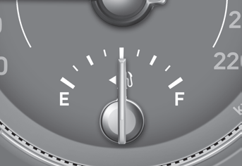
Fuel gauge

This gauge indicates the approximate amount of fuel remaining in the fuel tank.
Information
The fuel tank capacity is given in chapter 2. The fuel gauge is supplemented by a low fuel warning light, which will illuminate when the fuel tank is nearly empty. On inclines or curves, the fuel gauge pointer may fluctuate or the low fuel warning light may come on earlier than usual due to the movement of fuel in the tank.
Copyright © 2025 www.hvenueqx.com

