Hyundai Venue (QX): Auto Lighting Control System / Schematic diagrams
Hyundai Venue (QX) (2020-2026) Service Manual / Body Electrical System / Auto Lighting Control System / Schematic diagrams
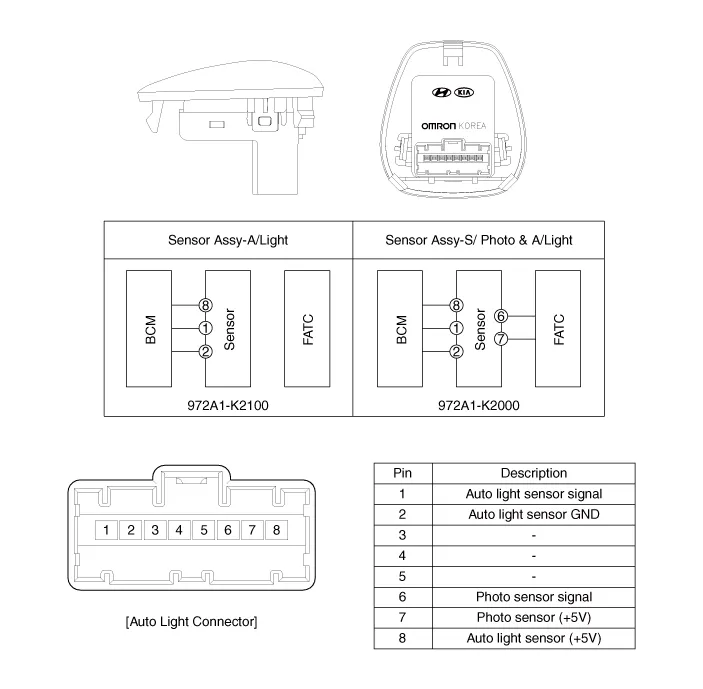
| Circuit Diagram |
Component Location 1. Auto light sensor 2. Head lamps 3. Integrated Body Control Unit (IBU) 4. Lighting switch (Auto) 5.
Inspection In the state of IGN1 ON, when the multi function switch module detects auto light switch on, tail lamp relay output and head lamp low relay output are controlled according to auto light sensor's input.
Other information:
Hyundai Venue (QX) (2020-2026) Service Manual: Heater Unit. Repair procedures
Replacement 1. Disconnect the negative (-) battery terminal. 2. Recover the refrigerant with a recovery / recycling / charging station. 3. When the engine is cool, drain the engine coolant from the radiator.
Hyundai Venue (QX) (2020-2026) Service Manual: Heater & A/C Control Unit (DATC). Components and components location
Categories
- Manuals Home
- Hyundai Venue Owners Manual
- Hyundai Venue Service Manual
- Electronic Stability Control (ESC)
- Remote start
- Warning and Indicator Lights
- New on site
- Most important about car

Copyright © 2026 www.hvenueqx.com - 0.0135