Hyundai Venue: ESP(Electronic Stability Program) System / Rear Wheel Speed Sensor. Repair procedures
Hyundai Venue (QX) (2020-2025) Service Manual / Brake System / ESP(Electronic Stability Program) System / Rear Wheel Speed Sensor. Repair procedures
| Removal |
[Rear Drum Brake Type]
| 1. |
Loosen the wheel nuts slightly.
Raise the vehicle, and make sure it is securely supported.
|
| 2. |
Remove the rear wheel and tire (A) from the rear hub.
|
| 3. |
Disconnec the rear wheel speed sensor connector (A).
|
| 4. |
Loosen the screw and then remove the rear drum brake (A).
|
| 5. |
Loosen the hub mounting bolt and then remove the hub (A) from torsion
beam axle.
|
[Rear Disc Brake Type]
| 1. |
Loosen the wheel nuts slightly.
Raise the vehicle, and make sure it is securely supported.
|
| 2. |
Remove the rear wheel and tire (A) from the rear hub.
|
| 3. |
Remove the rear brake caliper.
(Refer to Brake System - "Rear Disc Brake")
|
| 4. |
Loosen the screw and then remove the rear disc brake (A).
|
| 5. |
Disconnec the rear wheel speed sensor connector (A).
|
| 6. |
Loosen the hub mounting bolt and then remove the hub (A) from torsion
beam axle.
|
| Replacement |
| 1. |
Remove the rear wheel hub bearing assembly.
(Refer to Driveshaft and Axle - "Rear Hub - Carrier")
|
| 2. |
Fix the rear hub bearing assembly (A) on the vise.
|
| 3. |
Check the direction of the sensor cap (A).
|
| 4. |
Remove the sensor cap by hammering on a gap between sensor cap and hub
bearing assembly using a scraper (A).
|
| 5. |
Check if distorted or damaged the tone wheel or encoder (A).
|
| 6. |
Position the sensor cap to the same direction of sensor cap connector
(A) as you checked before removing.
|
| 7. |
Install the sensor cap (A) with the special service tool (09527-AL200).
|
| 8. |
Install the rear wheel hub bearing assembly.
(Refer to Driveshaft and Axle - "Rear Hub - Carrier")
|
| Installation |
| 1. |
To install, reverse the removal procedure.
|
| Inspection |
| 1. |
Measure the output voltage between the terminal of the wheel speed sensor
and the body ground.
|
| 2. |
Compare the change of the output voltage of the wheel speed sensor to
the normal change of the output voltage as shown below.
|
 ESP OFF Switch. Description and operation
Description
1.
The ESP OFF switch is for the user to turn off the ESP system.
2.
The ESP OFF lamp is on when ESP OFF switch is engaged...
Other information:
Hyundai Venue (QX) (2020-2025) Owners Manual: System Maintenance
Cabin air filter [A] : Outside air, [B] : Recirculated air [C] : Cabin air filter, [D] : Blower [E] : Evaporator core, [F] : Heater core The cabin air filter is installed behind the glove box. It filters the dust or other pollutants that enter the vehicle through the heating and air conditioning system...
Hyundai Venue (QX) (2020-2025) Owners Manual: Manual Temperature Control Mode
The heating and cooling system can be controlled manually by pushing buttons other than the AUTO button. In this case, the system works sequentially according to the order of buttons selected. When pressing any button except the AUTO button while using automatic operation, the functions not selected will be controlled automatically...
Categories
- Manuals Home
- 1st Generation Venue Owners Manual
- 1st Generation Venue Service Manual
- Rear Combination Light Bulb Replacement
- Remote Key
- Lighting control
- New on site
- Most important about car
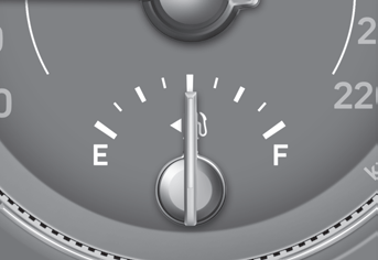
Fuel gauge

This gauge indicates the approximate amount of fuel remaining in the fuel tank.
Information
The fuel tank capacity is given in chapter 2. The fuel gauge is supplemented by a low fuel warning light, which will illuminate when the fuel tank is nearly empty. On inclines or curves, the fuel gauge pointer may fluctuate or the low fuel warning light may come on earlier than usual due to the movement of fuel in the tank.
Copyright © 2025 www.hvenueqx.com


